This post is a little different than my usual content - but I wanted to share an experience I had dealing with a very odd software (or hardware?) bug with the Raspberry Pi Pico microcontroller.
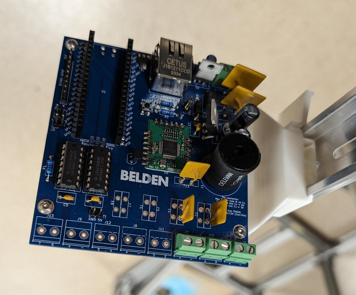
To set the scene, I am in the process of programming my ARGB Controller board - see below. The code mainly just listens for RGB data using the sACN / e1.31 protocol, and then outputs that to WS2811-style strips. The PCB gives the Pico an Ethernet interface, a polyfused 5V and 3.3V power supply, and a high speed 5V level shifter for the 8 LED outputs. It can passthrough the input 24V power at up to 12A (with a 2oz copper board), or supply 5V with it's onboard 5V 3A power supply that can take in 7-60V.

An LED board prototype (Pico not connected, slots into the bottom right headers)
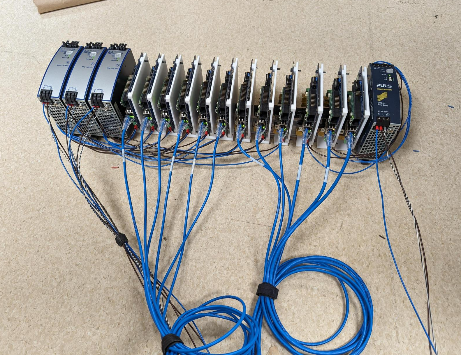
I\'ve got 13 of these boards for a large scale robotics project with Belden, powering and controlling thousands of LEDs through a robust industrial Ethernet network.
And for the most part, the code worked fine. There was some issues along the way, like the Pico randomly crashing, this ended up being due to the relatively slow polling the Arduino-Pico library's LWIP does to the W5500 ethernet chip, not keeping up with incoming packets, and running out of memory. There was an additional bug that also made it use more memory than in should so it crashed pretty quickly. But the amazing @earlephilhower of the Arduino-Pico project fixed that bug and added interrupt-driven connections to the W5500, completely solving the issue even with thousands of packets per second being blasted to the Pico.
After that, it worked great! I ran into a roadblock getting FastLED to work with RGBW strips, and it also has some quirks with compiling for the Pico somewhat randomly, so I switched to Adafruit_Neopixel which doesn't have any issues with that.
But then after I had concluded all my debugging, got everything working, I unplugged my USB serial connecyion to the microcontroller, and it just stopped. The LEDs froze. I double checked that the e1.31 streamer on my laptop was still running, I could still ping the ethernet interface of the board, but it was like the CPU locked up.
Ok, so somewhere in the code I accidentally waited for the serial connection to exist. So I took a look it the code, didn't really find anything. But just in case I removed every reference to the Serial interface, commented out every print statement... and it still froze the moment I unplugged my laptop. The Pico is still powered by the board, so it's not losing power - it's onboard indicator LED stays on.
I tried (actual) debugging with SWD instead of serial, and it would seemingly bounce around some core mutexes and then the debugger on my laptop would hang until I plugged back in the USB serial cable.
Unfortunately I didn't really have time to fully debug the issue and find a root cause in the code, with full time classes in my senior year of a Computer Engineering degree and a part time engineering job, but I did eventually discover that it was not Serial related, but the precense of 5V at the USB port / VBUS connection.

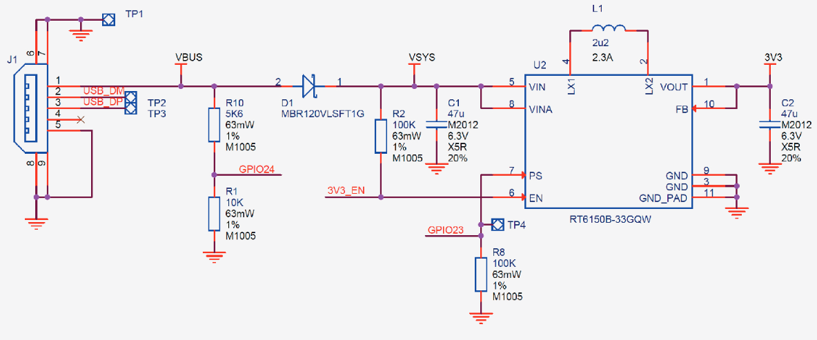
Looking at the powertrain diagram of the Pi Pico from the datasheet, we can see that the USB power gets fed into VBUS, which has a voltage divider going to a sense pin GPIO24, and then goes through a diode to become VSYS, the main power source for the power supply.
We know the power is getting to the power supply just fine because the LED stays on. But that GPIO24 is very interesting. Because my PCB powers VSYS directly, so VBUS is only powered when my USB cable is plugged in.
I confirmed by probing various points and providing power to the pin directly, that the code is locking up when GPIO24 is LOW. Now, if this was a common bug, surely someone would have noticed this by now, right? Well, I found through trial and error that this freeze only happens with the Adafruit Neopixel OR FastLED - which both use the PIO and DMA among other things. But it wasn't the act of using or writing LED data the pins, simply initializing the pins and then never writing any data to them causes it to lock up.
So, simple fix - use a solder bridge to bridge VSYS and VBUS pins. Well, of course it wasn't that simple. Since VSYS was at 3.3V, and now VBUS, that goes through the voltge divider which is pretty much a flat 1.85V, which is too far from the expected 3.3V of a logic high on a data pin. So the pin registers that as a LOW (0).... and locks up.
Okay, scrap that, I then had idea #2. What if I make the GPIO24 pin an INPUT_PULLUP, where it is connected loosely to a pullup to 3.3v connection, to trick it into then reading a HIGH signal?
Well, that didn't work either. The internal pullup was weaker than the effective pulldown of the voltage divider so it was still a logic LOW.
So after 30 hours of experimenting, I decided to do both at the same time. Bridge the pins together to get 1.85V, then maybe doing INPUT_PULLUP will then do a little bit more?
And it totally worked. The voltage went from 1.85V to 2.05V with the pullup mode, which was seemingly just enough to be considered a logic HIGH... and the code didn't halt.
But that was just a fluke right? I tried it on all 13 boards, and all 13 froze, until I made both the solder bridge and the INPUT_PULLUP mode, then they ran fine.
And these 13 boards have been online for about 3 months now, not a single reboot or halt.

12 of the 13 LED boards crammed on a DIN rail with power and ethernet connected
I'd love to figure out what the hell happened in there one day. But for now, my next revision of the PCB will use 5V power in instead of 3.3V. And maybe the bug will disappear with the new RP2350, if the hardware has anything to do with it.