As part of the Illinois Tech Robotics Club, I've designed a few PCBs to be used for various tasks.
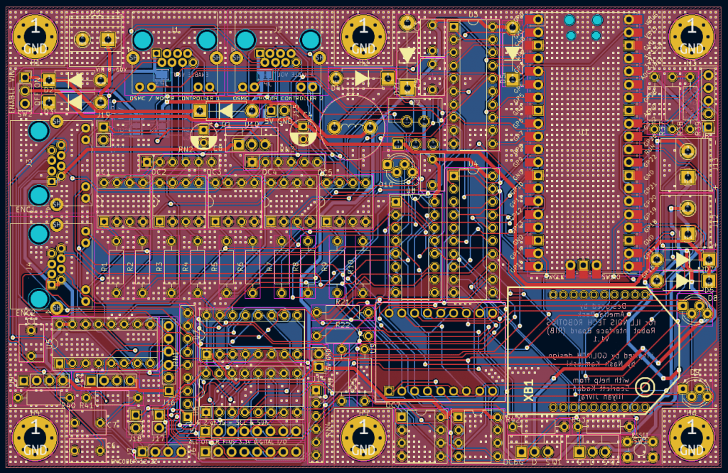
The first PCB is the RIB - the Robot Interface Board. This board is designed to connect and centralize all of the sensors, motor controllers, remote controls, etc of our robots (100-300lb competition heavyweights). The board makes heavy use of the Raspberry Pi Pico (W) because of it's PIO allowing us to read quadrature encoder states without interrupts, Bluetooth and WiFi connectivity, and great performance & flash space. Previously, many of our robots had 3-5 Arduinos: 1 Arduino Mega as the main controller and 2-4 Arduino Unos or Nanos to handle each their own quadrature encoder and extra peripherals. This board can do all of that and much more, though for a lot of that I have to give credit to the Pico, not my design.
What my design does make simpler is building and maintaining the robot. Previously, all of our robots had a rat's nest of wires crisscrossing each other, and there were no schematics or any documentation, so if a wire broke or something.... good luck!
So essentially, I've taken an optimized version of every robot circuit we could need on any of our robots, and flat-packed it into a PCB. So the older robot that run on 25V batteries and motor controllers from 2001 will work, and the robot with some FIRST robotics motor controllers and 12V batteries will also work.
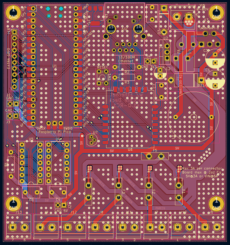
It also has an onboard power supply that pulls power from the main robot batteries. In previos robot designs, the microcontrollers ran off of a separate battery.
Of course, you can also use a separate battery. The RIB can run on 5V directly or any voltage from 7 to 60V, so it should be easy to find a way to power it.
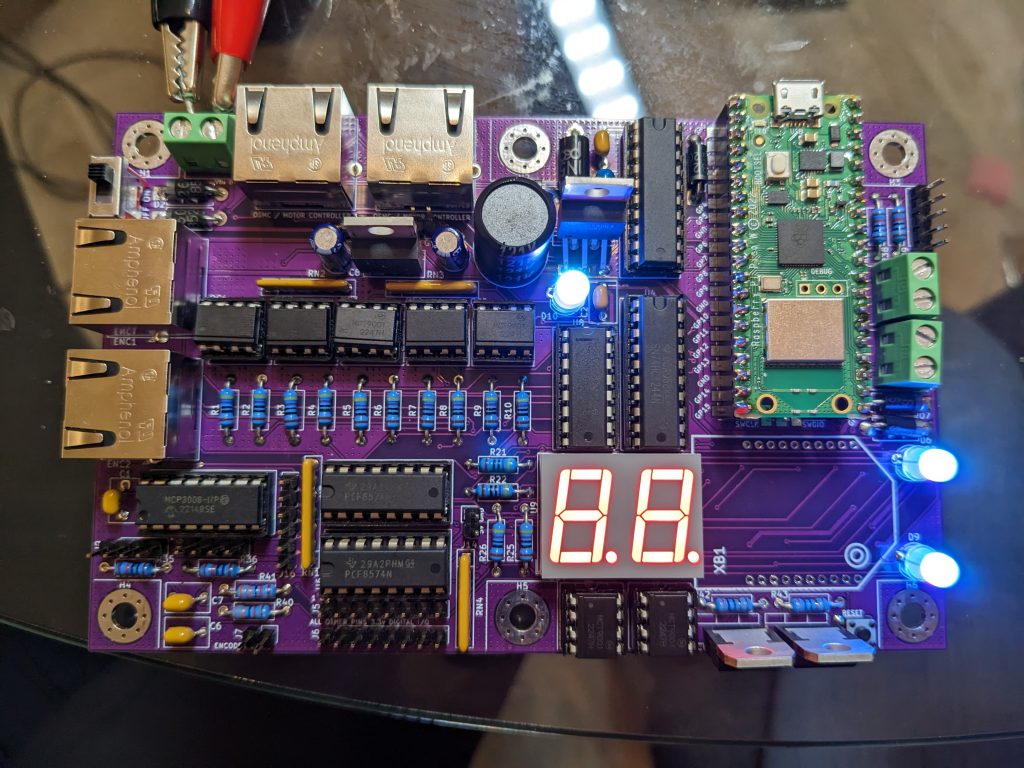
The first power up test of the RIB version 1 release. The board has since been fully validated and is actively in use on multiple robots.
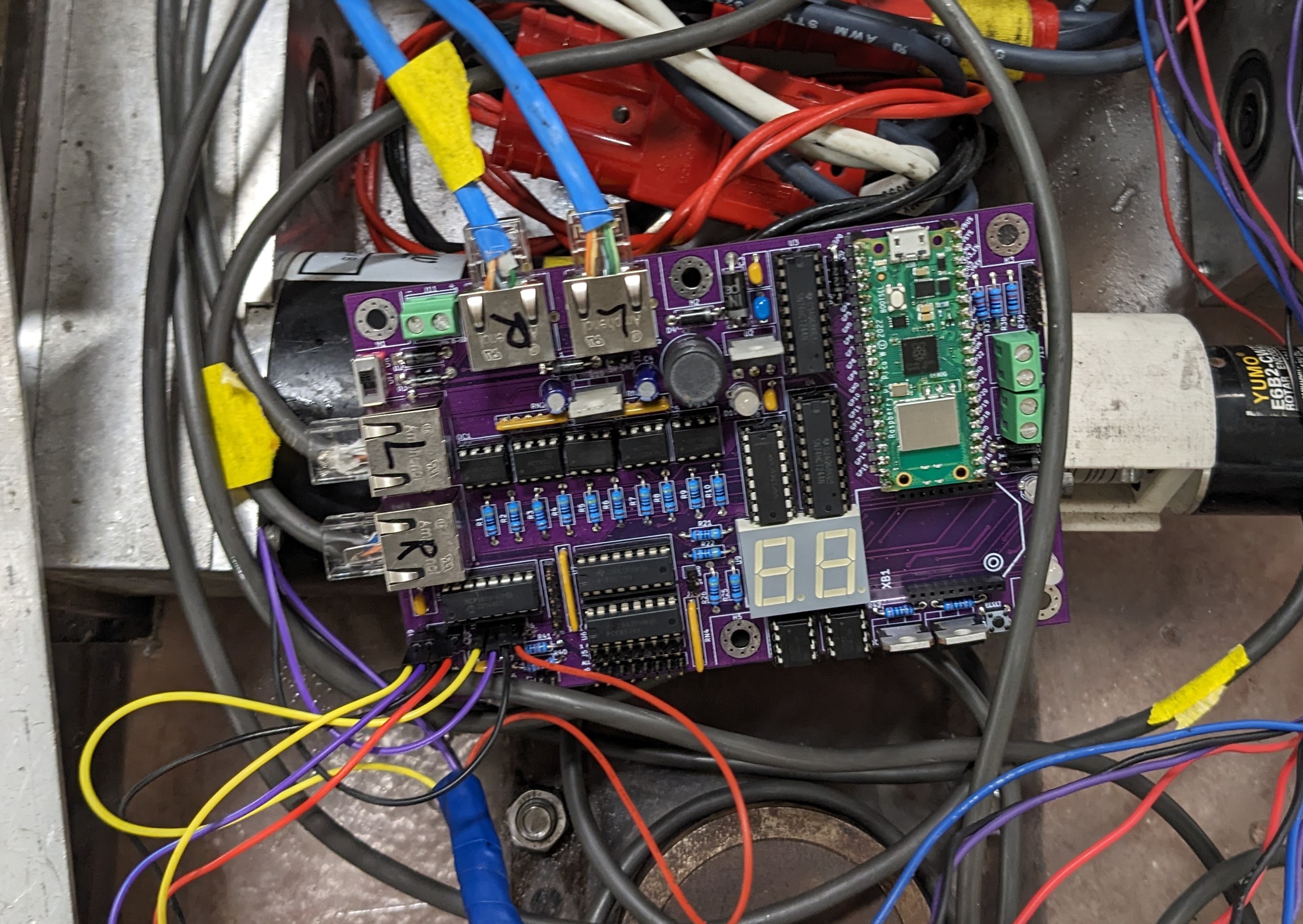
A quick and dirty deployment on ITR Goliath with motors & OSMCs, encoders, and current monitoring connected.
All digital outputs for anything high power (i.e. motor controllers) are connected with optocouplers, so there is a physical isolation to protect the board from reverse voltage feedback. On the 2001 motor controllers we use (OSMCs), their failure state is to dump the full voltage of the battery down the data lines. Which is not great, but with the optocouplers it won't damage anything.
*Now why in the hell are we using motor controllers from 2001 that blows up whatever is connected if there is no active protection circuit???
Because they are open source, insanely high power, can be daisy chained for even higher power, can be modified with higher rated components for even higher power, and are incredibly cheap compared to every competitive motor controller. Yes, I really searched basically the entire internet looking for something better. But there really isn't anything else that can put out 14kW after 10 years of use without breaking a sweat - for $100.
You can see the source files for the RIB, component lists, BOM, etc at this repository: https://github.com/illinoistechrobotics/rib
Anyways - went on a bit of a rant there - but this is not the only board I designed. I'm also in the process of validating another design - an addressable RGB controller, supporting LED strips that run at any voltage between 5 and 48V. There's a lot of similarities with the RIB - I'm using a similar, but higher power 5 & 3.3v power supply, it uses the Pico, the same terminal blocks... you get the idea. For 5V strips, the onboard 5V power supply has been beefed up to allow it to power around 50-100 LEDs. When running at a higher voltage, like 12 or 24v, the input voltage is passed through to the LEDs instead of the 5V power supply output. This allows for easily several hundred LEDs to be powered "through" the board until you hit a current limit (around 12A) when using the higher voltages. Of course, you can also power the LEDs separately, and use the board for only the data lines - and there, you can run essentially unlimited LEDs off of it. The Pico's PIO shines once again, allowing it to do precise timing across 8 LED data channels without bothering the CPU much at all, and each data line could address thousands of LEDs.
I will also release the source of this design once I validate it's function and settle on a final version (for now).